Micro Controller for Drift Guiding with the ST4
Problem and Idea
The following is a little project that addresses an problem that many astrophotographers
of comets and asteroids have probably encountered at one time or the other.
The object moves along its orbit in front of the background stars. A typical
setup of telescope for photography and guide scope then has the following
list of positive and negative properties.
-
POSITIVE : You guide on the object that you want to image.
-
NEGATIVE : Bad luck if the object is too faint.
-
POSITIVE : The guide scope has a wide range of motion
to select guide stars.
-
NEGATIVE: Unfortunately the object moves!
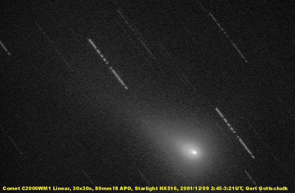
SOLUTION : You pick an fairly bright and suitable guide star and
purposely makes little guiding errors during the exposure. If those errors
are carefully calculated the resulting image will show the stars trailed
to elongated lines and the target object (comet / asteroid) has stayed
in one spot.
There are illuminated cross hair eyepieces available today which incorporate
graded scales in their field of view. With some calculations and alignment
of the eyepiece the guiding will then require to move the star along the
scale at a certain rate of drift.
For automated guiding the famous auto-guider ST4 made by SBIG
has been around for a while. This device keeps a guide star fixed at a
position in the field which makes it suitable for fixed deep sky objects
but it fails on moving targets.
The ST4 has among other a serial port interface to connect it to an
PC. This has been used by Paul
Mortfield who wrote a PC program (Comettrk)
that periodically send commands to the ST4 to move the guiding star to
new slightly modified coordinates. Consequently the guiding is compensated
for the motion of the comet. I would like to thank Paul here for the work
he put into the development of the algorithm and the PC software.
Hardware
A drawback of the above solution is that you now have to carry a laptop
PC to your imaging location. If you don't have a fixed observatory this
can be cumbersome process. I was looking to eliminate the PC and came up
with a solution that utilizes a micro controller module to send the corrective
commands to the ST4. For the module I selected the CPU_1A1 made by PMB
Electronics. I like it because it's small. I made a small circuit for
it to allow for LED display and a few push buttons.
Here is a picture of the little module with my circuit attached to the
ST4.
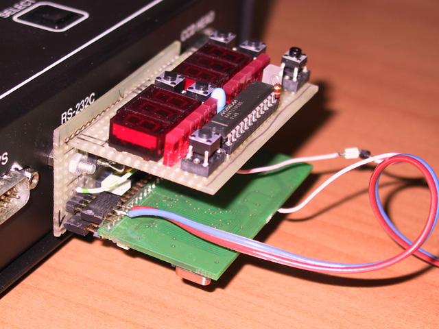
On top is the little display board. Below the CPU module and attached
to the ST4 box the adapter board for power supply and serial connection.
In my setup I have modified the ST4 serial connector to carry +5V on pin9
(which is not used by the ST4 or the PC). This eliminates the need for
an extra power supply to operate the module. Mechanically the design can
easily be modified to fit different form factors. So far I only have a
hand drawn schematic for the circuit. If somebody wants to create an electronic
version of the schematic I'll be more than happy to post it here.
My own schematic is drawn on paper. I have taken a digital picture of
it and post it below.
Schematic PDF file (1.8MB)
Software
Development of the software was the next step. It is written in assembly
language. Obviously different users may want to modify it to suit their
particular needs. To allow for that I have put the source text on this
page as well as a binary version that can be loaded into the hc11 module
and run using default settings. If anybody wishes to develop the software
further please feel free to do so as long as you mention e as the original
author and send me a copy so I can post it here.
I have used the asm11 assembler which can be freely obtained here
as download.
A few more comments on the source text. There are a few variable settings
at the top.
*************************************
* Major switches for assembly control
*************************************
DEBUG EQU 0
ST4_90 EQU 0
GGMODE EQU 0
DEBUG is for software development. It requires the module to be connected
to a PC.
ST4_90 is 0 if the ST4 is directly attached to the guide scope. Use
1 if you have a 90deg prism.
GGMODE is to preset some variables for my own use. (I was getting lazy
entering my guide focal length every time)
Download Files
Assembler source text
Binary file S19 format
Usage
Reset
The butten (lower left in my board) causes a reset. This also starts the
communication with the ST4 during which an interrupt is sent to the ST4.
This causes any guiding in progress to terminate.
Enter
This button (lower right in my board) functions as enter key.
Display
There are two 3 digit 7-segment LED displays, a 3 color LED and two LED
ramps. The color codes for the three color LED are as follows.
-
RED : There has been a fatal error. An error code is displayed and the
CPU is halted.
-
YELLOW : The module is initialized and expects parameter input.
-
GREEN : Guiding is running. Periodic corrections are sent to the ST4
Operation
Upon reset the software requires input of the guiding focal length. The
left LED display shows 'FL'. At the right the up / down keys can be used
to select the desired value. The number is entered in 10mm increments.
A display of '123' means 1230mm guiding focal length. The focal length
can only be entered once after reset. If it has to be changed you have
to push reset again.
Next the drift parameters are entered. The drift angle is shown in the
left, the drift speed in the right display (my board). The angle counts
north-east-south-west and is selected in one degree units. Up / down keys
are again used for selecting the desired values. The drift speed is selected
in the same manner. Units are arc seconds per minute. Press the enter key
when both parameters are selected. At this time the drift guiding will
start. (ST4 has to be in guiding mode at this time. See below)
Next to the numerical display are two LED ramps. They show a count down
timer for both axis to the next correction command.
Typical operation ST4
ST4 and the module are connected and the wires to the mount are hooked
up. The module starts up when the ST4 is power up. Internally the ST4 takes
a little while for power up and does not respond immediately to the hc11
module. This may cause a timeout (red LED). Press reset on the hc11 module
once here and things should be fine. Next the software asks for the guiding
focal length and you enter the correct value.
Next a suitable guide star is located, focussed on the ST4 and the
mount is calibrated. Start the ST4 guiding mode. At this time the drift
parameters are set. Press enter and the guide correction will commence.
Start the exposure. After the exposure is complete reset the hc11 module
and the next cycle can begin.
Summary
I hope people may find this little project interesting. Please contact
me if you have questions or want to contribute to the project.
(c) 2002 Gert Gottschalk